-
Replace the CRT in a NANAO MS9 monitor -
It is the year 2011
Update
1: here >> Toying with a magnet &
24 kHz
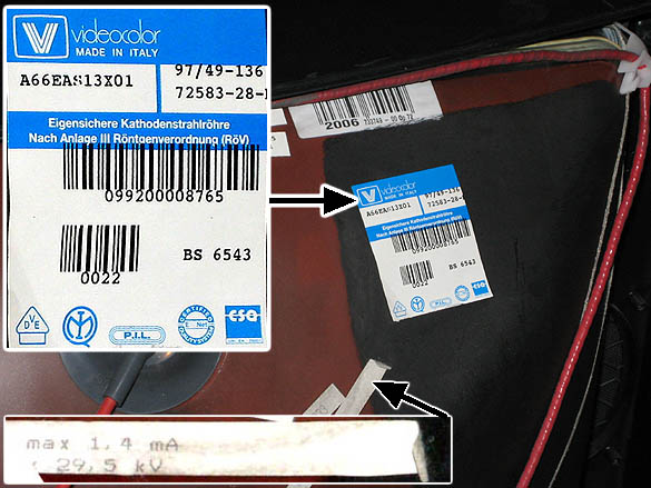
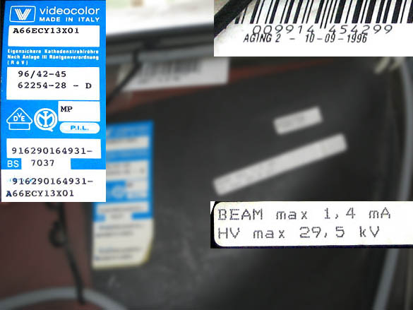
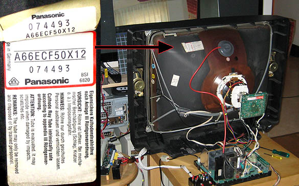
Update 2: here >> Videocolor A66EAS13X01
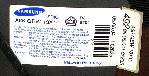
Update 3: here >> Funai TV, Samsung
A66QEW13X10
Update 4: here >>
the Quintrix
Update 5: here >>
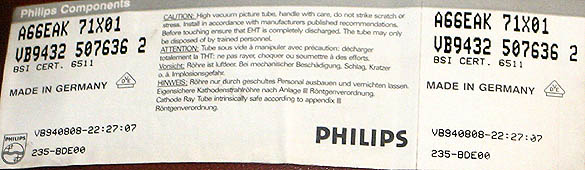
Philips mono-TV with A66EAK71X01 CRT
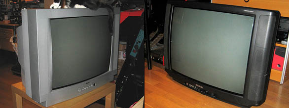
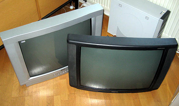
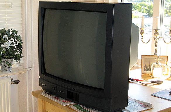
You will need a TV, either a 29'' (A68 ...) or a 28'' (A66 ...) will
do the job just fine. 28'' are easy to come by in your trash and they
are more common here in EU than any 29'' CRTs. Problem is that you will
have a tough day trying to mount a 28'' CRT in your original NANAO frame.
There's this tiny little centimeter spoiling all the fun.
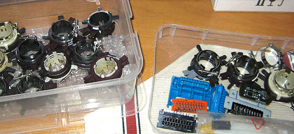
The CRT has to have compatible pinout with MS9 which has 'K' (cathodes/color
guns) on pins 6, 8 and 11, the G2 is on pin 7 and heaters are on 9 and
10. The socket is a standard 12-pin type with pin #1 keyed on both sides.
There are a number of socket types out there so be sure to check its
form. Another useful tip would be so save the original neckboard of
your TV to trace the pinout. Usually there's text printed on the board
telling you what positions are 'K', ground, G2 and Heaters.
Your CRT should, not necessary but obviously, also have a similar shape
as the MS9 original 29'' CRT. Meaning that if you use a diamond shaped
CRT your geometry will be affected, and don't even think about the Trinitrons
(if at all compatible). The MS9 can compensate for certain pincussion,
trapezium and horizontal liniarity, but if you're after a proper replacement
look for a semi-flat (slightly rounded) CRT. They are the most common
CRTs, at my local garbage disposal anyway.
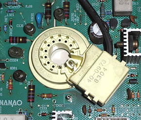
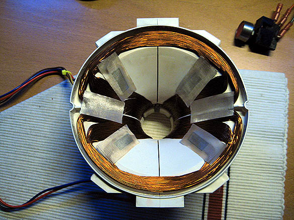
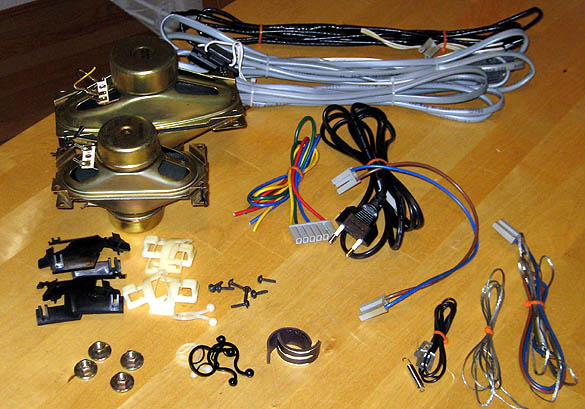
Socket of
NANAO MS9
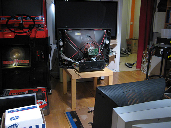
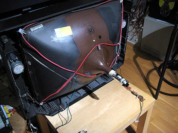
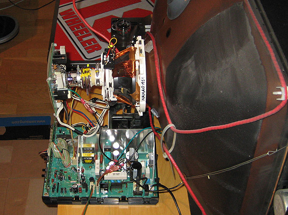
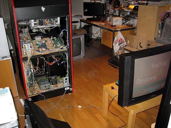
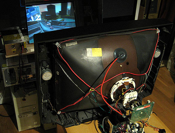
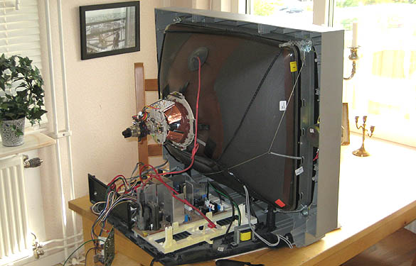
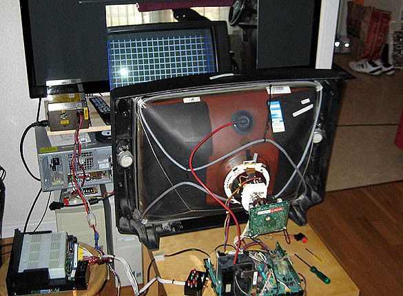
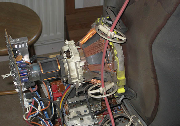
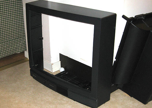
Start by taking off the rear cover of your TV. You know how. If not, you should stop right here and go practice a safer sport. I'm not particularly concerned about your health, but on a side note let me just mention that the voltages here can kill you.
In this case I decided to try to use the original yoke with my Nanao MS9 chassi. I've checked the resistance and it was similar to the MS9 yoke.
At first we need to adapt the wires to the MS9. So we cut off any of the connectors leading to the original TV-chassi. We will hardly need the TV's connectors.
- Degauss. Two wires. If you're lucky there will be a matching connector here. Or you will just need a two pin round type connector here. A micro-switch can be used to activate a degauss. Check the switch rating first.
- Neckboard to Dag (grey painted area on CRT's back) Ground. One pin round type for MS9, or just a MOLEX crimp.
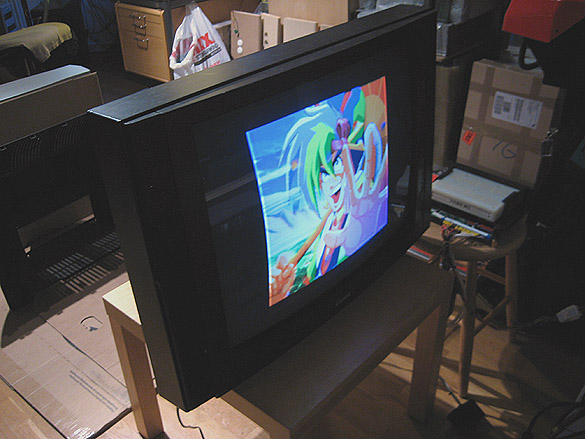
We have picture!
... oops, no. That wasn't very pretty, was it. We know why this is. The
TV-yoke has got the same Ohm values as our MS9 yoke, however it does have
other properties which normally wouldn't concern us unless we wanted a
dual-sync monitor.
Yes, inductance. Something I rarely need to measure, so I simply don't
care. I have an MS9 original yoke!
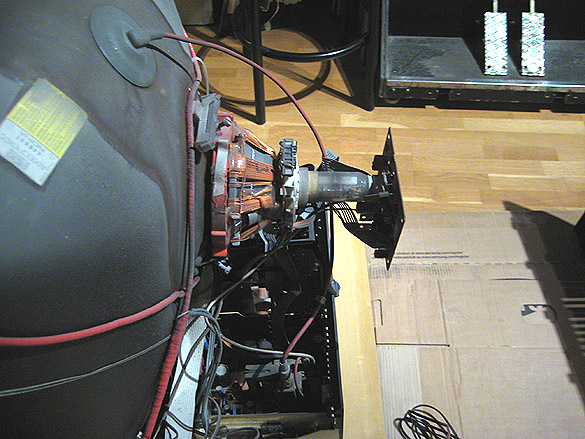
So, off it
goes!
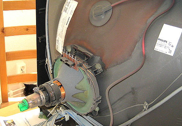
This can be a painful job to do. Prepare a sharp knife, a flat head screwdriver,
and some sort of cloth to clean up around the area. Start by unscrewing
the clamp around the neck.
And try not to touch the anode-hole and the dag at the same time, or you
will be in need of a break. Discharging a CRT isn't a guarantee it will
stay discharged.
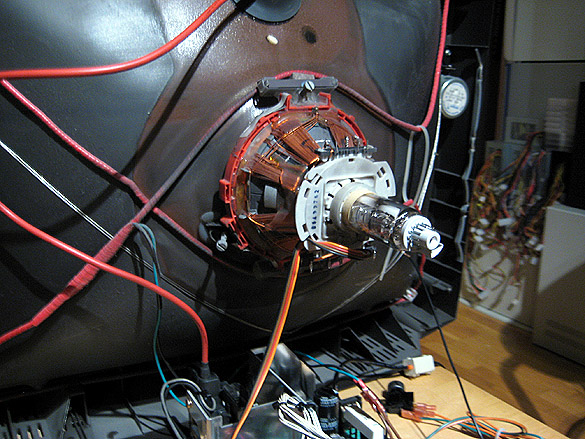
A deflection yoke is usually fastened by it's three, or four rubber wedges.
They use silicone/rubber glue in the factory so it *can* be removed. However,
practice great caution not to stab yourself in the other hand with any
of the tools while doing it.
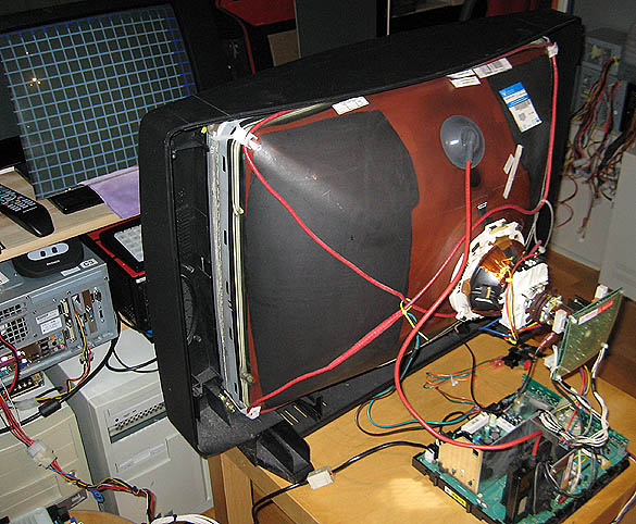
Before
you attempt to twist the TV yoke off the CRT neck, loosen and pull the
ring-set if present. My TV here didn't use magnetic 'convergence rings',
but many CRTs do use them. Save them as they can be used again.
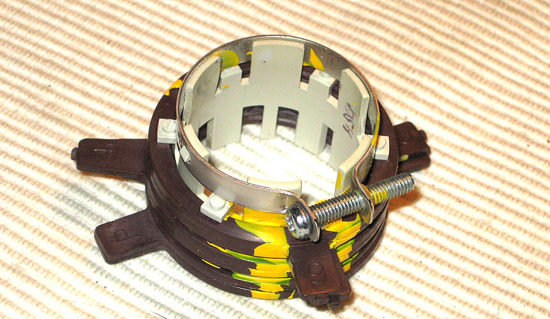
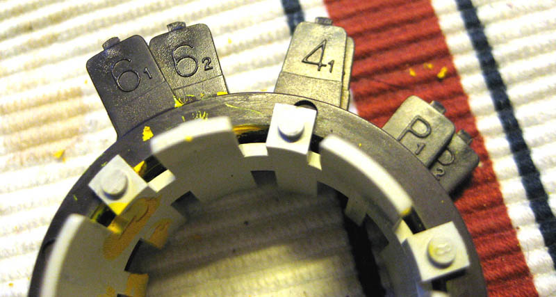
This picture shows the MS9 original ring-set, here in its original orientation.
Let us assume that the screw on the clamp is 12 o'clock. The 'P' rings
(that's "purity rings") are closest to the yoke on the MS9
neck. They're oriented towards 3 o'clock. Next comes the '4' ring-pair
which are at about 5 o'clock, and last is the '6' pair which is about
1 o'clock.
These were hell loosening up. I had to use a sharp knife and work my
way ring by ring, and manually scrape the yellow glue off each ring
before assembling the ring-set back together.
Here you see the inbetween rings that are there to separate the ring-pairs from each other. They should all be nice and clean to rotate smoothly, although not too smoothly because you want a bit resistance to make them stay in place once your adjustments are made.
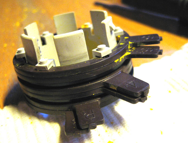
The order of rings. I'm not sure how it affects the convergence if you assemble the rings in a different order, but I wouldn't.
We will get back to the rings later. But for the time enough about the rings. We've got a yoke to install!
Now we've got our original NANAO MS9 yoke and rings installed on our CRT.
Let's power it up to see what we can see!
Now. If you placed the yoke all the way front on the CRT, you will need to pull the yoke backwards a little bit to allow for a certain margin in movement. This will also remedy any discoloration that may appear. Tighten the clamp screw a little just untill you feel you can still adjust the yoke.
This is a good time to make a degauss.
Use one rubber
wedge at 12 o'clock to secure the yoke for the moment, and then insert
the other wedges around to stabilize it.
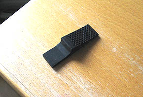
.. yes, that's
a rubber wedge.
If you want use rubber glue or silicone to secure the wedges use it scarcely
as you may want to remove it later in life.
Don't forget to degauss before fixing the yoke permanently.
Back to
the rings.
Did you know that there are CRTs with an internal, built-in, convergence
control? Yes, you get an *almost perfect convergence* with these. It's
fantastic! I've seen it. Unfortunately this is not it. So, you will
need to use the ring pairs to produce as good and clean lines as you
possibly can.
First leave the P-rings in 3 o'clock position and focus on the "4"-pair.
These control the RED and BLUE converging. Basically you must achieve
a solid MAGENTA. Easier if you just REMOVE the GREEN input, you'll see
better.
Then the "6"-pair rings, these controls the MAGENTA converging
on the GREEN, (so connect the green back on). Toy with it untill your
back hurts, as this is simply a chapter about patience and endurance.
You CAN make it look good if you just toy with it long enough. And in
time maybe, just maybe you will become a master, as I am.
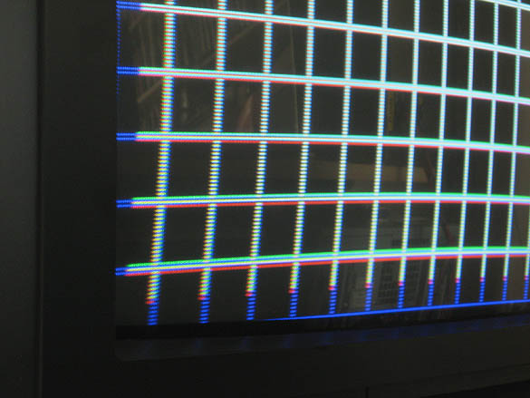
A tip: Splitting the ring-pairs, meaning that you turn them relative
to each other (not just turning the ring-pair around the neck) will
affect the grid lines converging in X-formation. Imagine a pair of scissors
opening and closing. And turning the complete pair toghether affects
the horizontal line's as well as vertical line's positions. Hard to
comprehend? That's why you need to *toy around* with it to understand.
It's like a skill-game.
* * *
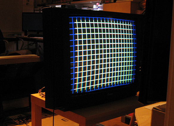
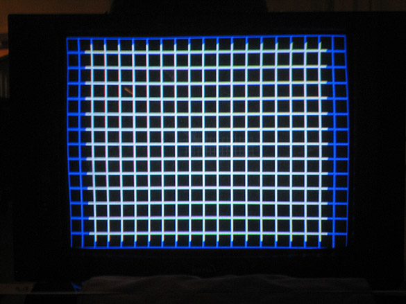
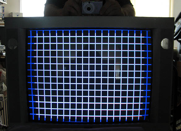
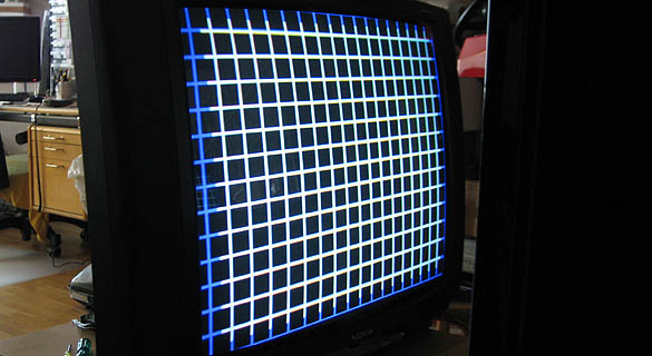
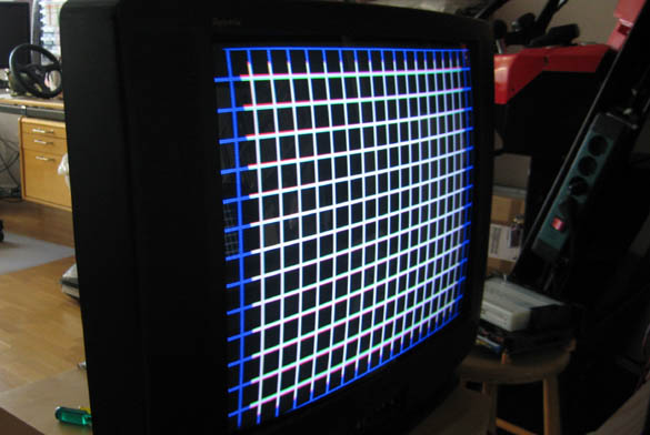
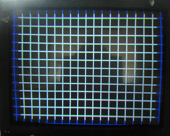
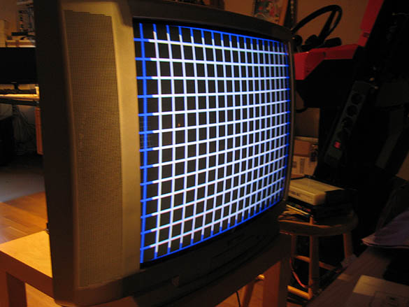
Ok. So
now we have a nice grid on our new and totally burn-in free CRT. Depending
on variations in CRT shape we tend to get slight variations in geometry.
However not outside the tolerance for a med-res monitor. We can compensate
pincussion and any trapezium deviations, if present. The trick is to
produce a good enough grid with an acceptable convergence of RGB to
make the overall picture look good. There isn't such a thing as a perfect
picture. CRT is all about minimizing the tolerances and pushing the
limits to smaller detail. Simply put: it's analog.
There are high-res monitors with chip control of every square inch of
the screen. And the NANAO MS-2931 (tri-sync with OSD) usually shows
a pretty bullseyed grid regarding geometry and convergence. But our
MS9 is mainly a low-res and med-res display, and as such has rather
generous tolerances. But hey, don't complain, it's made in Japan!
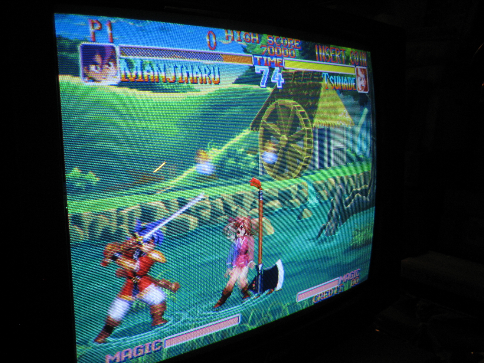
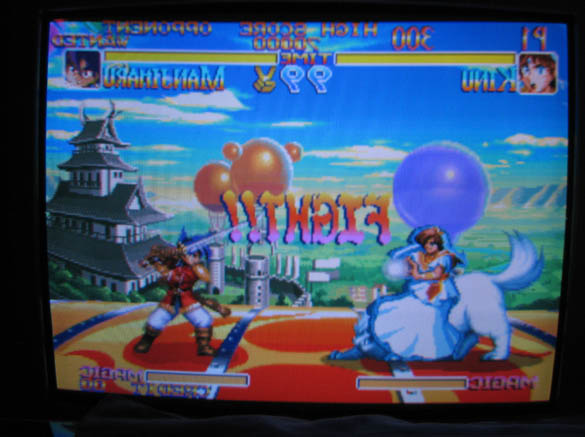
Right. Ready for gaming?
Oh, you probably wonder how I've achieved these juicy and vibrant colors in my screenshots?
Well, let me tell you that it is another chapter about adjusting and balancing the RGB of an RGB monitor. Which is basic theory about toying with the RGB 'drives' and BIAS the color temperature to a perfect 'neutral' - very difficult if you're a cat.
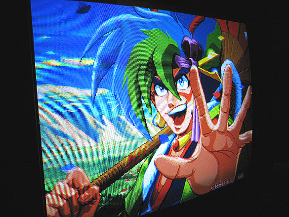
I just cannot focus with such a sexy ass on the screen.
One degauss, one moment of yoke adjustment, and I guess I was a little lucky.
(The horisontal banding is a camera phenomenon. You don't see it IRL.)
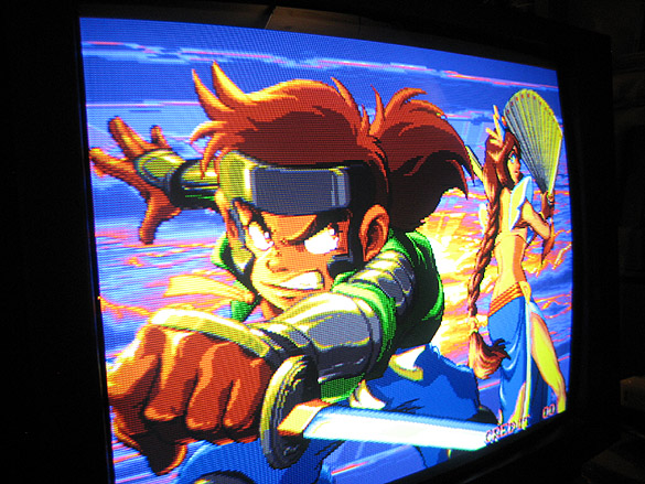
Some of my stuff I use to kill cute little unicorns with.

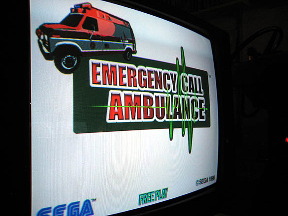
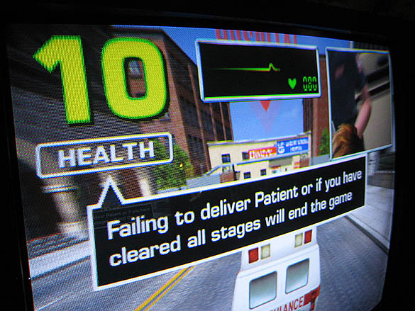
Testing
in 24kHz mode with SEGA Model3 Emergency Call Ambulance.
And
toying with a magnet
.. no, not the pliers! The MAGNET!
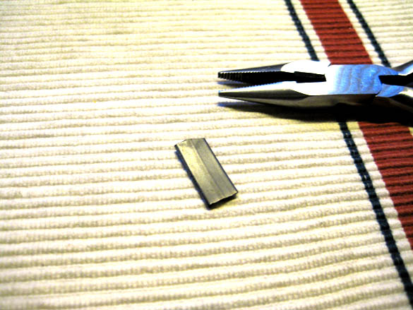
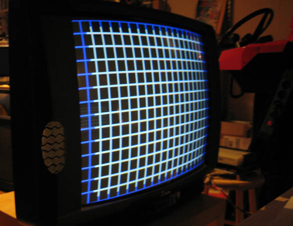
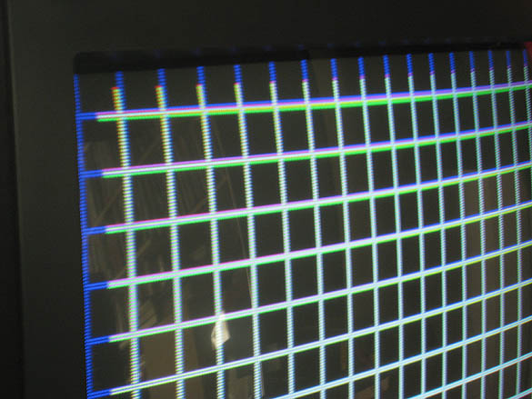
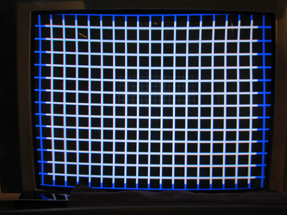
The edge of the yoke is actually molded in a way that allows for extra magnet placing. Hold the magnet to the edge. Slide it along the edge if you want, and watch the grid.
You notice that the corner on the left is pointing outwards slightly, yes? More than the right corner, that is sure.
Why?
- Because I've corrected the right corner with the magnet.
The rule of this principle is simple: Where I place my magnet around the yoke's edges, the grid will stretch outwards, just like rubber cloth would. And the stronger the magnet, the more it stretches.
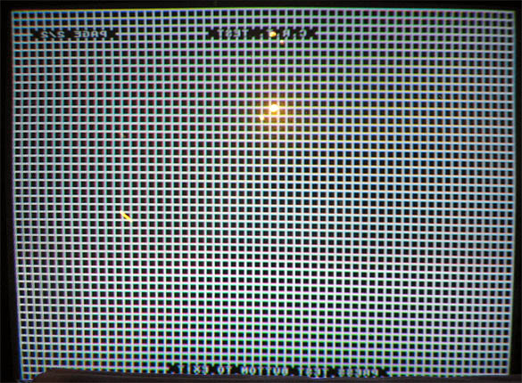
Can you see the upper right corner changing shape?
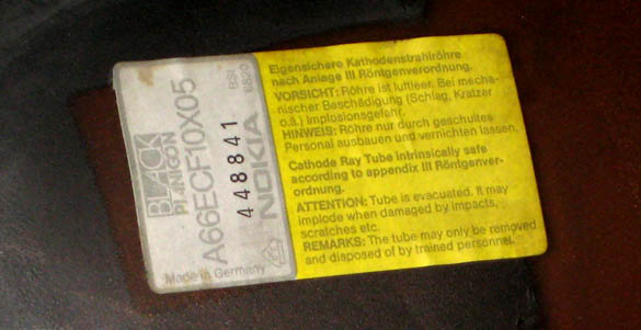
Can you read what it says there.. ? "Black planigon"? Really? 'Black Planigon' - it must be a very, very advanced CRT. Perhaps some kind of new technology that we've never heard about, something really great. Planigon. Wow! I have a Planigon CRT, I must be very lucky.
Do not place magnets under the yoke if you want to stretch the grid. Only put magnets around the yoke edges, sides or closer to the coil if it will cause the desired effect.
Basically what this means is that after you're done with the rings, and you feel there's not much more improvement you can make to the convergence, this is what you will need to resort to.
There are a few ways you can do it: taping magnets directly into the yoke, or stick a plastic rod with a magnet taped to its top to gain more precision. The rod is then secured with tape or glued. Or, gluing magnets directly onto the CRT. Anything to move that beam!
This evening I've set up my MS9 at 24 kHz, and this time it's not NeoGeo but the SEGA Model 3 and Emergency Call Ambulance. (Yes, it's me, the notorious swede with the Ambulance project.)
But tonight it's friday night, so let's make some DANGER!
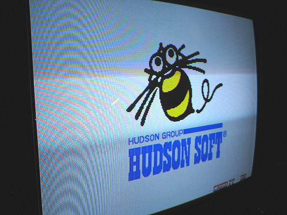
Let's take a look at what we can see in 24 kHz.
Nice and bright, great CRT that 'Black planigon'.
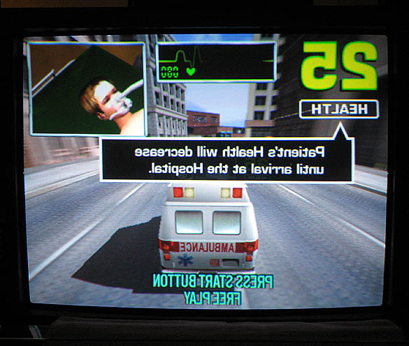
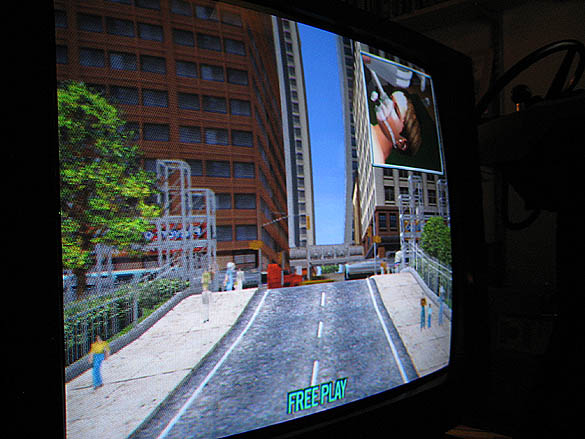
From this angle you can both work and see what you're doing on the screen.
I remember this spring (2011) fixing my friends 15k Intervideo chassi with this particular CRT, and already then I noticed its low intensity tolerans. I tweaked the focus as well as possible under a lower than usual intensity, and got it pretty good with sharp scanlines and clear pixels. But as soon as I increased contrast the focus degraded, even before I had a semi bright image.
Just that same thing I experienced this evening with the Nanao MS9 chassi on this CRT.
Probably this CRT was made either intentionally to handle a max beam current of 1,4mA, or, it was tested OK with the beam current set to 1,4mA, where any higher Amp would degrade the focus.
Either way it passed the A-grade test for TV use. Strange.. In any case this means that it can't display as sharp image as other CRTs at the same intensity.
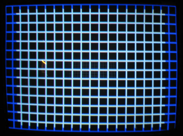
Have a look.
This is as good as the focus gets under this intensity circumstance. If
I were to lower the contrast some, the focus would improve. But since
the intensity is already rather low I don't want to decrease it any further.
Also, I did measure the heater voltage, which in Nanao MS9 seems to be
4,8V (sampled with a regular multimeter). However this is not the problem
as there is plenty of glow under the glass. Plus, remember that the Intervideo
chassi had the same problem with this CRT.
Yes. It's a problem, but fortunately not one that I will have to live
with. This CRT is going far, far away, already this evening.
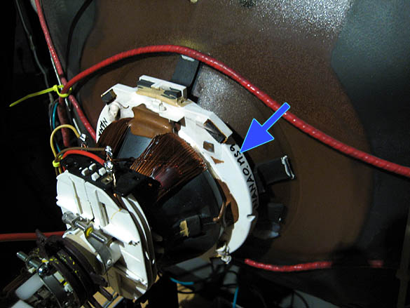
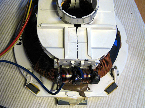
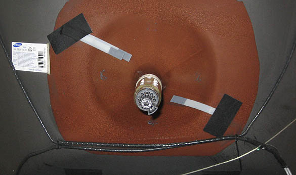
1. The degauss-coil retention clamps
2. the dag-lead
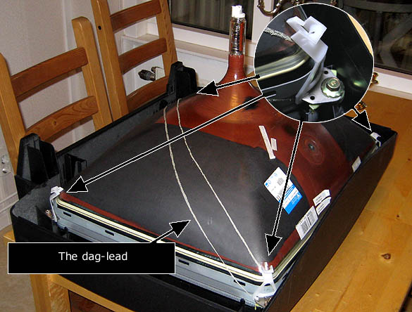
Removing the old rings and yoke. Scraping the glue off the glass with a sharp knife to finish cleaning with white spirit and then a damp cloth. Nice and clean, that's how I like my stuff.
Then again, perhaps I should remove the taped magnets on my Nanao yoke, to start a fresh tuning? Every case of yoke + CRT is one exclusive instance. They all have their small deviances and personalities.
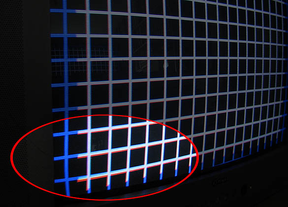
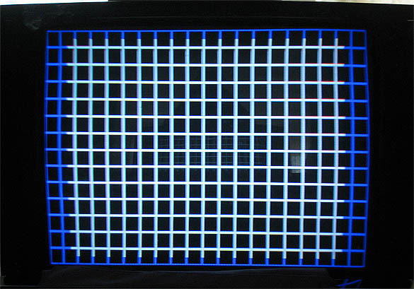
Using the
Nanao original magnet rings and yoke we are looking at a pretty OK grid
here.
But ...
.. hm, ..
.. the convergence is slightly off at the lower right. Isn't it?
So, what can we do?
We can always try to swap the nanao magnet rings for the ones that came with the Samsung CRT!
And look
what happens, the convergence is at once nice and almost as perfect as
it gets on a 28'' CRT!
What did we learn?
- using the original parts that come with our CRTs as often as the situation
allows.
Meaning that even though the rings and yoke are physically close to each
other, they still are individual components that work independently of
each other.
A grid pattern doesn't get much better than this on a MS9. It's not perfect,
but well withing the tolerance of a 28-29'' low to mid resolution TV.
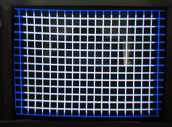
The conlusion here is that the A66QEW13X10 is good enough to serve as a monitor for my games.
* * *
Next up is the A66ECY13X01
This is however another Videocolor CRT. Again we see the interesting lable "1,4 mA".
The Videocolor brand is starting to get on my nerves. Especially since they are limiting the beam current for some particular reason. Why would you do such a thing? To save the phosphors?
Or would it surprise me?
Let us see.
With the MS9 rings and yoke, this Videocolor isn't as stingy with the intensity as the previous Videocolor was. It does show a slight bluring if I increase the contrast, but still, it is bright enough!
I am confident that I can use this CRT, so I will put an 'uncle grade-A' on it.
I'm not thrilled by this CRT, but I won't throw it away either. It's a good spare.
... I'm running out of space.
And, I still have a 28'' Quintrix to test.
Away it goes!
However, ... do you see? There's some wild red there at the corners. Both upper and lower corners here looks like they could use some convergence correction. So let's turn down the contrast a bit and tweak the focus so that we can observe the convergence better.
I've used an Atari test pattern here to challenge the convergence even more. A nice and bright CRT as this one should have its convergence tweaked some extra.
I'm using the Nanao ring-set and I keep trying to correct the green-on-magenta convergen, but it's just not possible due to the sad fact that the green grid is smaller than the magenta. And there's nothing I can do about it with stuff I have at hand.
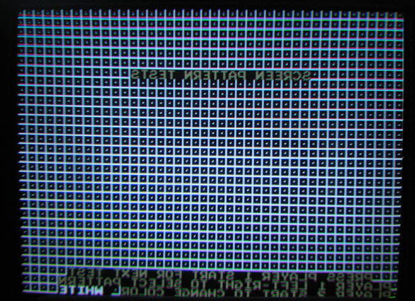
This makes the magenta lines going over the green lines at the upper portion of the picture, and vice versa the magenta lines goes under the green lines in the lower part of the picture. They never ever converge at the upper and lower portions!
I'm guessing that this A66ECF50X12 was made for the special purpose to have its convergence managed electromagnetically with the remote. I can't explain it otherwise.
I could never use it with my 24k med-res games. Sad fact is, I will never use this CRT.
.. am I a damn ''feinschmecker'' who deserves a spanking for binning a CRT such as this?
At least I won't be such a big hamster, after all.
Philips mono-TV with Philips CRT A66EAK71X01, and
Samsung TV with Thomson CRT A66EHJ13X38
Testing with a Nanao MS9 chassi, Nanao yoke & ring-set
Am I lucky? Or what?
Could it be that there's a difference between CRTs manufactured for electrically controlled convergence, and CRTs manufactured for manual ring-sets?
I don't know. It could be a coinsidence. But this CRT behaves very closely to how the Quintrix behaved.
In the upper portion of the screen you start to see deviations, already within a 15 cm diameter area. And at the topmost lines there's a scan line high difference between the green grid, and magenta grid.
Not acceptable.
Trying to corrent this, I used some rods, sticking under the yoke only to put the geometry off and still not correcting anything. Also, you see that the green deviance is horizontally equal, all the way from left to right side. *The green grid is vertically smaller*, and again there is nothing I can do.
Not acceptable at all in 24kHz games!
Thomson CRT A66EHJ13X38
To tell you some more history about it, the TV had a basic type of yoke with a magnetic strip around its neck.
This means that there wasn't any electromagnetic control of convergence.
.. but, what you cannot see on the photo, because the camera always compensates the light intensity some, is that the picture is a bit dark.
I did my standard proceeding with setting the brightness pot on the remote PCB to center, and then tweaking G2 to the degree where the background (black) raster is just visible. And the tweaking the contras to the degree where the scanlines are still clear, and not bluring. Then I check the focus pot to optimize focus, and last I tweak the contrast again with a slight increase.
One other phenomenon I'd like to mention about this CRT, something which I've only experienced wich smaller cheap chinese CRTs, is that the color balance, that's the BIAS of R, G and B changes as I change the contrast (!?).
Sorry, but not acceptable!
The remains of the Samsung TV, the Philips, and some Quintrix details are there as well. I take everything into consideration, and I don't throw out things that can be useful.
So what have we learned this far? - Are CRTs that have electromagnetic control of convergence creating slight problems when manual convergence rings are installed? And pictures with weak intensity, bluring as contrast is increased, are typically brands like Videocolor and Thomson?
.. untill I find some more TVs in the garbage to gut and test.