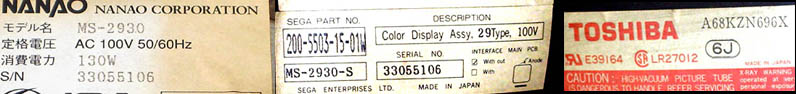
Taking care of an old SEGA monitor
MS-2930-S
I wonder why.
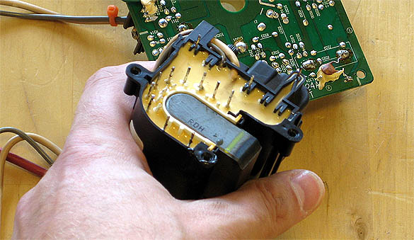
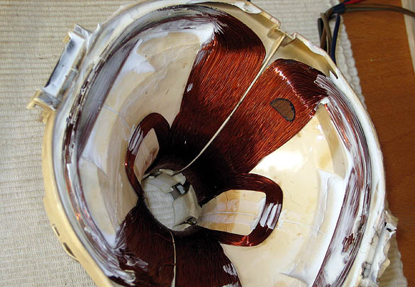
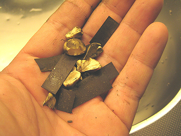
Dried up tape and only crumpets left of what used to be some sort of induction inlays, or magnetized plastic.
And, .. dear Joseph, Mary and a baby dinosaur! Is that the yoke body cracking up?
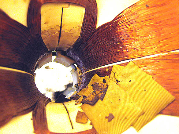
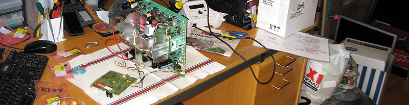
This monitor has been locked up inside a hot place for a very long time.
What can we do?
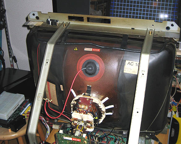
No, not oursevles. The yoke and CRT area that we want to work with!
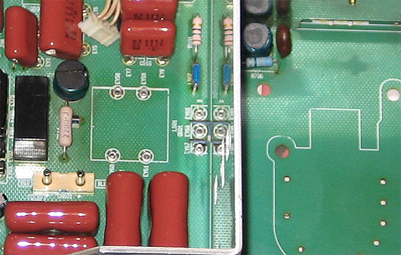
Putting the chassi aside for later re-capping, we remove the daughter board and some of the larger components, to be able to clean it better. We ... What's that?
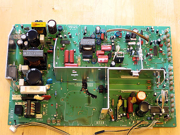
It looks as if someone pooped on this chassi. I doubt it's the flyback, so that leaves us just one option.
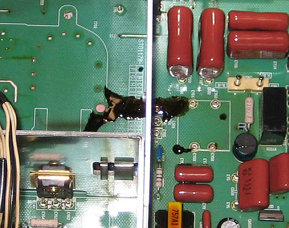
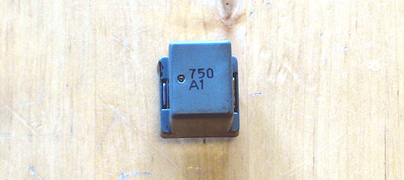
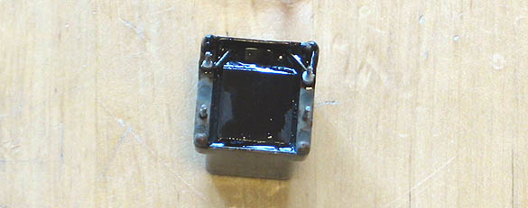
So the pooper must be taken care of before it has another 'accident'.
I've got information that this chassi was operating inside one of these small japan made cabinets. Yes, those white plastic 29'' ones that look like astronaut-helmets.
Don't these cabinets have vents!? They are very efficient monitor-killers. We can all agree on that. Who else would we blame for all that molten goop?
Usually monitors are specified to operate in the ambient temperature of maximum 40 *C. My guess is that it is much warmer inside these air-tight cabinets.
There are quite many electrolyte caps on this chassi, so we'd better make a map.
And here it is for you guys who actually want to go through with it: >> Cap-Map Large
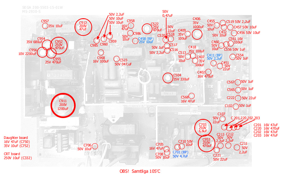
All 105*C
(BP) Bi-polar
|
Pieces
|
uF
|
Volt
|
|
1
|
2200
|
10
|
|
1
|
1200
|
200
|
|
1
|
1000
|
35
|
|
1
|
680
|
35
|
|
2
|
470
|
250
|
|
2
|
470
|
25
|
|
2
|
470
|
16
|
|
1
|
330
|
35
|
|
1
|
330
|
16
|
|
3
|
100
|
35
|
|
1
|
100
|
16
|
|
1
|
47
|
200
|
|
7
|
47
|
16
|
|
5
|
22
|
50
|
|
2
|
10
|
35
|
|
12
|
10
|
50
|
|
1
|
10
|
250
|
|
1
|
10
(BP)
|
25
|
|
1
|
6,8
|
250
|
|
1
|
4,7
(BP)
|
50
|
|
6
|
2,2
|
50
|
|
1
|
2,2
(BP)
|
50
|
|
6
|
1
|
50
|
|
2
|
0,47
|
50
|
Work,
work work ...
...
work, work work!
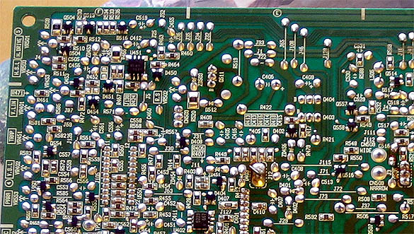
You should use a solder sucker for the larger caps, but when removing the smaller caps in densely populated areas, use a smaller wick. Or you could accidently suck up a surface mount component next to your target. As you can see, the board is full of innoscent bystanders.
Be quick and be precise, like a ninja.
... now where were we?
Yoke!
... with refreshments!
I'll
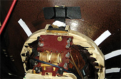
cut the process short and show you the result.
Basically
you impregnate the yoke as much as you can so that cracks and crevices
are shut and fastened.
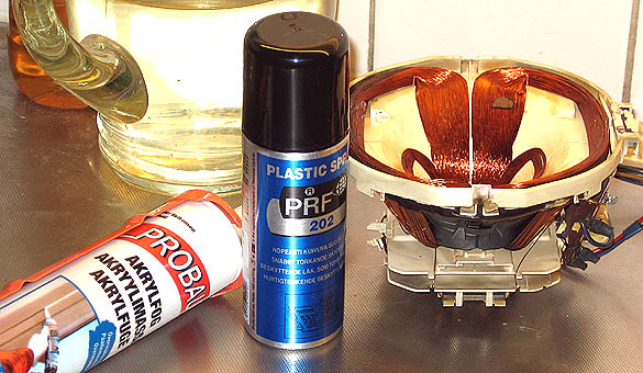
No special moves or combos, just put the stuff in there. I used the spray
first, generously, and let dry. Then the white smear.
The spray is called 'Plastic Spray' and it's for circuit boards and electronics.
The white stuff is called 'Akrylfog' in swedish. I don't really know its
composition, but it's sticky, rubbery and flexible. So it does the job
I need it to do.
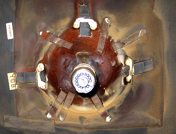
This should shut the yoke up eternally.
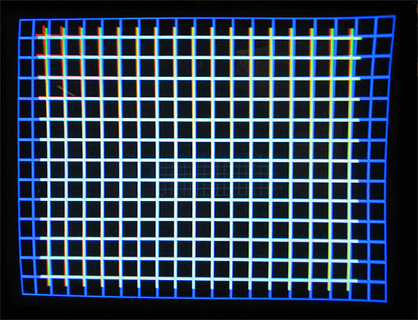
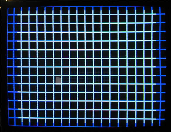
| So, now we have a nice yoke, a really nice and clean restored MS-2930-S trisync chassi, and a pretty CRT. All waiting to be asseblmed and powered up. But there is one small problem still that we need to take care of, otherwise we won't have the picture this monitor was initially blessed with. |
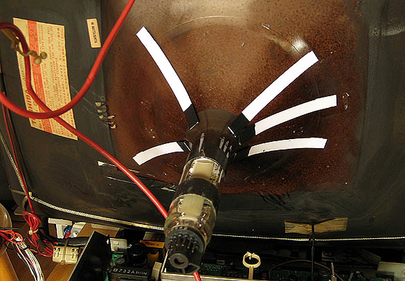
So how can we create some inductance around the cathode guns to correct the convergence?
We cut out a few 10 x 100 (mm) pieces of hardened paper. Normal paper should be OK, but I wouldn't, no.
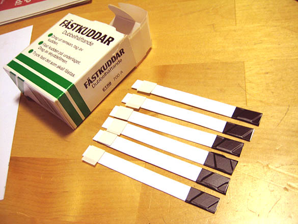
Chip off accordingly few pieces of the knife's blade and use one layer of isolation tape around it.
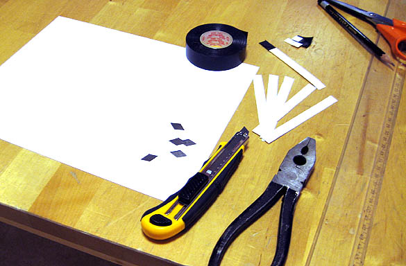
Securing these 'inductor-sticks' can be done by simply taping them to the CRT, or as I've used some of Camilla's double sided sticker tape.
Important is that the metal part is isolated. Why, I think I don't need to explain.
But with no more than one layer of tape. because we want to move this little rod freely under the yoke, looking for its 'sweet spot'.
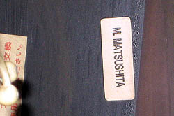
After all it is his work we're restoring here.
Here's a trisync that will last another 20 years, hopefully.
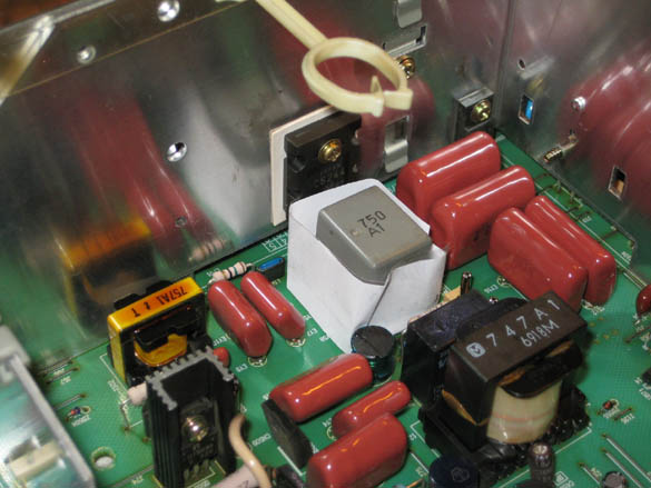
Then secure the yoke from at least three directions with the rubber wedges and duct tape. And, to further inhibit rotation and vibration, some white goop between the yoke and wedge.
* * *
|
Thank
you guys. It means alot to be able to help out regaring these beautiful old monitors. Don't worry about hazardous shocks or lethal accidents. We all learn by experience. If we only followed theory, we would be stuck in the library. The
bottom line is: |